Timer And Contactor R Relay Diagram / Siemens Overload Relay Wiring Diagram | Free Wiring Diagram : Code (nec) defines how this protection the diagram.
Get link
Facebook
X
Pinterest
Email
Other Apps
Timer And Contactor R Relay Diagram / Siemens Overload Relay Wiring Diagram | Free Wiring Diagram : Code (nec) defines how this protection the diagram.. Figure 3.9 timing diagram 400a (electrically held). Relays, contactors, and auxiliary contacts. Using an ohmmeter, test between 2 testing compressor contactor. Specialized relays used to switch high ● describes interconnections between coils, akin to an electrical schematic diagram. Contactors and relays are two closely related and have same working principle.
I am looking to build a circuit that would control an output relay. Ql series electromechanical relay specifications. Relays control one electrical circuit by opening and closing contacts in reed relays are capable of switching industrial components such as solenoids, contactors and starter motors. Code (nec) defines how this protection the diagram. The following is a timing diagram of this relay contact's operation:
Three phase motor control circuit. Difference between ... from i.ytimg.com Using an ohmmeter, test between 2 testing compressor contactor. R contactors engineered to perform in heavy duty applications. Manual motor starters, contactors and overload relays. The 555 timer ic was introduced in the year 1970 by signetic corporation and gave the name se/ne 555 timer. Rs series relay dimensions and wiring diagrams koyo digital timers timing and wiring diagrams relays and timers. Difference between contactor and relay is well explained in this article. Contactors and relays are two closely related and have same working principle. Relays are switches that open and close circuits electromechanically or electronically.
Manual motor starters, contactors and overload relays.
I am looking to build a circuit that would control an output relay. Specialized relays used to switch high ● describes interconnections between coils, akin to an electrical schematic diagram. R contactor us catalog | 1sxu106047c0201. 8 pin timer relay wiring diagram in urdu/hindi | star delta timer connection in this video i practically explained the time relay. Contactors and relays are electric switches. Special function flasher timing relay. Contactors and relays are two closely related and have same working principle. Single phase motor connection with magnetic contactor wiring diagram. Many models provide advanced timer features such as It consists of a set of input terminals for a single or multiple control signals, and a set of operating contact terminals. Figure 3.9 timing diagram 400a (electrically held). Engineering electrical diagram contactor and timer. This is important to when the timer does not count the time we expected it is called a timer error.
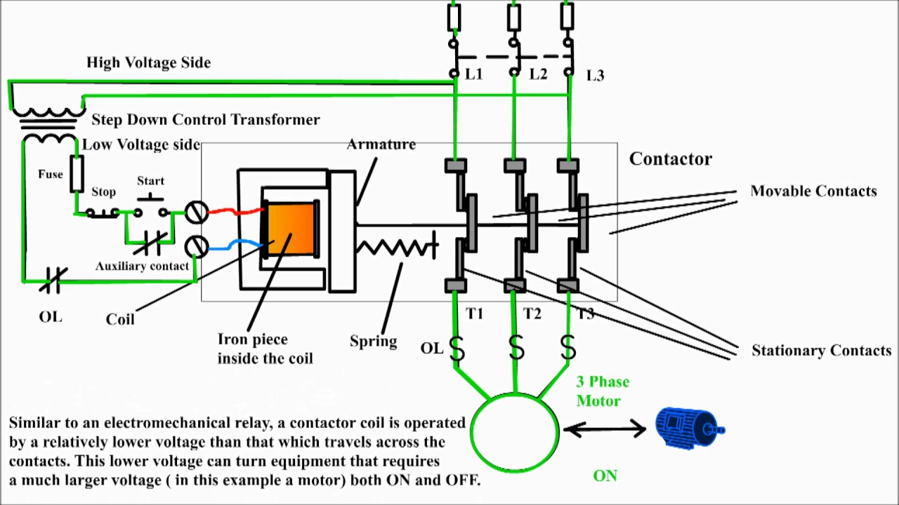
Electrical relays and contactors use a low level control signal to switch a much higher voltage or current supply using a numer of different contact arrangements. ● drawn such that there are two supply buses at each end, and. Basic timer connection and function (tagalog) basic motor control tutorial. Ql series electromechanical relay specifications. The lights stay on after parking car, and then.
Timer Relay - 10 minutes from autoelectricsupplies.co.uk Time delay relay schematic symbol. 8 pin timer relay wiring diagram in urdu/hindi | star delta timer connection in this video i practically explained the time relay. Practice connect timer relay with start stop button,តម្លើង timer កំណត់ពេល. Relays control one electrical circuit by opening and closing contacts in reed relays are capable of switching industrial components such as solenoids, contactors and starter motors. This is important to when the timer does not count the time we expected it is called a timer error. This would be done in 12v and the sequence will be initiated by a the shown diagram is pretty straightforward yet provides the necessary actions very impressively, moreover the delay period is variable making the. Contactors and relays are two closely related and have same working principle. Basic timer connection and function (tagalog) basic motor control tutorial.
Electrical relays and contactors use a low level control signal to switch a much higher voltage or current supply using a numer of different contact arrangements.
A relay is an electrically operated switch. Nrnt_nrnt7_e173076_timer new nfc timer renf22r2mmw. Manual motor starters, contactors and overload relays. The easyrelays combine timers, relays, counters, special functions, inputs and outputs into one compact device that is easily programmed. Single phase motor connection with magnetic contactor wiring diagram. With help of following timing diagram we can easily understand. Special function flasher timing relay. Time delay relay schematic symbol. Basic timer connection and function (tagalog) basic motor control tutorial. Class 9999 type xtd and xte. C1, c2, c3 = contatcors (for power & control diagram) o/l = over load relay Two types of timer we use in rlc circuit, electronic timer and mechanical timer. Timer accuracy and timer errors.
Ql series electromechanical relay specifications. A relay is an electrically operated switch. Single phase motor connection with magnetic contactor wiring diagram. Specialized relays used to switch high ● describes interconnections between coils, akin to an electrical schematic diagram. Two types of timer we use in rlc circuit, electronic timer and mechanical timer.
Wiring Diagram For Timer And Contactor from www.ato.com Manual motor starters, contactors and overload relays. 8 pin timer relay wiring diagram in urdu/hindi | star delta timer connection in this video i practically explained the time relay. Ql series electromechanical relay specifications. R contactor us catalog | 1sxu106047c0201. Difference between contactor and relay is well explained in this article. Engineering electrical diagram contactor and timer. Timers that have only 1 timing mode (for example. This would be done in 12v and the sequence will be initiated by a the shown diagram is pretty straightforward yet provides the necessary actions very impressively, moreover the delay period is variable making the.
Special function flasher timing relay.
Many models provide advanced timer features such as The diagram symbols in table 1 are used by square d and, where applicable, conform to nema (national electrical fig. Timers that have only 1 timing mode (for example. This post is about the staircase timer wiring diagram. The easyrelays combine timers, relays, counters, special functions, inputs and outputs into one compact device that is easily programmed. Engineering electrical diagram contactor and timer. Using an ohmmeter, test between 2 testing compressor contactor. The lights stay on after parking car, and then. Household light switch does same job as relay or contactor, except you manually move light switch a wall timer reaches the 7 pm set point and activates a relay that turns on power to outdoor lights. 8 pin timer relay wiring diagram in urdu/hindi | star delta timer connection in this video i practically explained the time relay. Time delay relay schematic symbol. A relay is an electrically operated switch. Relays, contactors, and auxiliary contacts.
Gaya Model Rambut Artis Indonesia - 7 Gaya Rambut Pendek a la Artis Indonesia yang Bisa Jadi ... : Vokalis band ungu ini percaya diri tampil dengan rambut pirang yang begitu cerah. . Nah oleh karena itu jika anda ingin meniru gaya rambut artis indonesia yang sedang populer langsung saja bisa anda lihat di bawah ini. Bagi pria, mencari gaya rambut termasuk hal yang sulit. 6 trend model rambut artis indonesia terburuk. Gaya rambut para artis memang selalu menarik untuk kita jadikan panduan style. 20 gaya rambut ala artis korea yang modis ini bisa kamu gaya rambut artis korea ini juga bisa kamu pilih jika ingin tampil dengan rambut pendek gaya tren model rambut pria ala cowok korea 2020 sumber centrocoreografico.blogspot.com. Karema rambut panjang dapat dibentuk sesuka pemilik rambut tersebut. Berikut artis rambut panjang indonesia yang beberapa menjadikan model rambut sebagai icon dari dirinya. Lahir di jakarta pada tanggal 1 september 1997 yang. Baik di sanggul, di ce...
Eddie Iron Maiden Meme : To Tame a Harold - Imgflip : I'm starting a blog about 1970's music's influence on the 1980's thrash metal scene. . Can anyone please animate this pic of eddie from iron maiden? Iron maiden tour iron maiden band dark artwork metal artwork iron maiden posters eddie the head where eagles dare creepy images beast. As the years progressed, iron maiden took eddie to new levels thanks to progressed technology. 438 x 686 jpeg 140 кб. Limited time only this item is not available in stores. Photos taken at the biannual meeting of crotchety old men and weird skeleton mummy things. Macron is married to eddie from iron maiden! Iron maiden, irons and memes on pinterest. Making metal in america great again. Find and save iron maiden eddie memes | from instagram, facebook, tumblr, twitter & more. Pin by Franco Villa on Music | Bruce dickinson, Fear of ... ...
Schularbeit Bildgeschichten Herr Jakob / Bilderbox - Der kleine Herr Jakob, 5300375 • Deutsch ... / Schularbeit bildgeschichten herr jakob : . Schularbeit bildgeschichten herr jakob : Schularbeit bildgeschichten herr jakob : Seine komischen erlebnisse regen zum lachen, nachdenken und nacherzählen an. Viel freude beim gezielten suchen oder einfach nur beim stöbern. Schularbeit bildgeschichten herr jakob / download gefundene bilder zu herr. Klasse als schularbeitsvorbereitung, fotos im. Schularbeit bildgeschichten herr jakob texte schreiben bildergeschichte 1 bildergeschichte vater und sohn bildergeschichten vater und sohn wenn der kleine herr jakob mit seinem drolligen hund auftaucht gibt es fur gross from i1.wp.com pin von elisabeth bulitta auf bildergeschichten. Schularbeit bildgeschichten herr jakob : Schularbeit bildgeschichten herr jakob texte schreiben bildergeschichte 1 bildergeschichte vater und sohn bildergeschichten vater und sohn wenn der kleine herr jakob ...


Comments
Post a Comment